Home of the Tiny Cedar Flea

Author: Duncan (Page 1 of 4)

Laminar flow on a Pou?

The Tiny Cedar Flea (TCF) uses the NACA 23112 airfoil which stalls at just over 12 deg Angle of Attack.  Or does it?

Enter Axel Darling, a highly regarded aerodynamicist and Flying Flea enthusiast who wrote in Pou Renew #41 as follows:

The French terminology can be a little confusing – so here’s a quick glossary:
Enterplan:  the positional relation of the two wings (i.e. the wing separation)
Eh:  The horisontal separation of the wings
Ev:  The vertical wing separation

“I found that there is a solid relationship to laminar flow at
equal entreplans. So, therefore I recommend 65/65,
70/70, 80/80 or whatever you choose, however the
greater the entreplan the better up to a point and more
specifically it relates to the vertical to keep a smooth
flow.”

Basically, Axel discovered that if the vertical and horisontal wing separations are identical, the airflow over both wings becomes laminar.  So the question is – why did it take so long to discover this?  In Axel’s words: “everyone has ignored [this] for decades because changes in Ev have little effect while turbulent”.  Every Pou ever built has very small horisontal wing separation but much larger vertical wing separation.  Some even have zero horisontal separation.  There is absolutely zero chance of laminar flow on these Fleas.  Axel’s claim isn’t just a theoretical dream – laminar flow over both wings with equal vertical and horisontal separation has been verified experimentally with wool tuft tests.

So what are the lessons to be learned from this?

  1. We need to have equal horisontal and vertical wing separation if we want laminar flow over both wings.  The “standard” wing separation on ALL fleas is impossible to produce laminar flow.
  2. As a consequence of the laminar flow, the NACA23112 airfoil as used on most modern Poux no longer needs to stall at 12 degrees, but incidence of up to 20 degrees can be achieved, giving a landing lift coefficient of close to TWO…
  3. And with this increased lift comes far slower stall speeds.

Axel concludes:
“In the final analysis, I found that starting at 90cm/90cm
[ED: i.e. vertical and horisontal wing separation] with any
of the most used aerofoils on Pou’s that they
remained in laminar flow all the way down to about
20cm/20cm. Of course below 50 or 60cm it isn’t of
practical use”

The TCF has vertical and horisontal wing separation of 70cm.  Right in the sweet spot.  Achieving this on such a small plane was no easy feat, and required the rear wing to be mounted inside the tail section, rather than on top of the turtledeck as is the case with all Flying Fleas of which I am aware, including the HM293 pictured below..

Current mini-project: sizing the nose

Hi.  One of my abiding challenges in this design is ensuring that the engine will fit in the nose.

I have a Generac 990 v-twin which I got from Valley Engineering when Gene was still there, and they were making engines.  Mine is the “Big Bad Twin” – a bored-out, tricked up version of the 35-odd HP original motor.  Mine pushes out 50hp, and weighs 53kg complete with twin exhausts, starter, AND redrive.  That’s a pretty sweet package.  I haven’t removed these items to weigh the bare engine, but I hope to do so soon.

However, I can’t find an accurate 3D rendering of the engine, and herein is my problem:  how to I sculpt the nose of the plane to ensure that the engine will fit?  If I had better CAD tools (or knew how to drive them better) I’d probably be able to do so.  But I don’t.  So here’s what I’ve decided to do:

I will build the firewall forward section of the fuselage (using the first seven formers only).  Then I’ll cover them with 3mm EPS foam from the local hobby shop.  That will achieve the following:

  1. The materials will be extremely cheap
  2. I can iterate the nose design indefinitely till I get it right
  • The first stage of the process is to mount the firewall forward formers on the strongback, and lay the foam strips – just as I would do using the Paulownia strips.  (Great practise, too).
  • Then I need to build an engine stand and mount the engine (see the accompanying pic)
  • Finally, I’ll take the two halves of the nose section, and attach them to the engine stand.  The engine will either fit, or it won’t.  If it fits, I’ll pop a bottle of Champers.  If not, the champagne will stay in the fridge, and I’ll return to the CAD and amend the volume of the nose till I get it right.

The engine stand will be on castors so I can move it around, and will have the bed-mount for the engine added to what you can see here.  Also – notice that the entire thing fits together without bolts or screws.  This means when I no longer need it, I can break it down and flat-pack it against a wall somewhere…  Construction material:  18mm plywood.


Rear wing incidence?

For historical reasons, Mignet’s Fleas had fixed incidence rear wings.  And it is one of the major flaws of the original design.

What happens is this:

  1. Let’s say the rear wing is fixed at 4 degrees incidence.
  2. At takeoff and landing, the front wing is inclined up to 12 degrees, producing most of the lift.
  3. However, as flight speed increases, the incidence of the front wing has to be lowered to maintain level flight.  However, the rear wing incidence is fixed, and as speed increases so does its lift.  At sufficient speed, the rear wing can actually overpower the front, and the nose of the plane begins dipping down.
  4. There comes a point where the front wing is no longer able to out-muscle the wing at the back, and the plane begins a nose-down pitch from which it is difficult to escape.  This becomes a limiting factor in the airspeed of any Pou.
  5. However, a variable pitch rear wing completely overcomes this limitation.  As the front wing incidence decreases, so does the rear wing.  The plane remains in equilibrium, and can fly as fast as it’s engine (or a dive) can propel it.
  6. Finally, when coming in to land, the rear wing can now be pivoted together with the front wing.  With both wings at (say) 12 degrees incidence, the plane now can produce far greater lift.  Which equates to slower landing speeds.
  7. One final piece of the puzzle is the “Pulga pitch control” wing on top of the tail.  With both wings inclined strongly on landing, the plane will have a tendency to pitch forward strongly.  Enter the “Pulga wing ” which acts in opposition to the two wings, producing a strong downward force to counter the forward pitch.  The result?  A smooth, co-ordinated landing at significantly lower speeds than before possible.

The blue circle in the pic below shows the bellcrank which controls the rear wing pitch.  If you prefer (for whatever reason) to keep the rear wing pitch constant, you simply set the pitch on the ground, uncouple the bellcrank from the controls and away you go.  On subsequent flights, you can adjust the rear wing incidence to suit your flying style, till you find your sweet spot.

And for the more adventurous – these will be a setting which allows left and right rear wing halves to be independently controlled.  So, for example, if coupled to the controls, the entire wing halves can be rotated in opposition to each other, so that they act as giant ailerons.  Naturally, the amount of differential deflection will need to be very small, and I am nowhere close to figuring it out.  Probably, once I’m familiar enough with the TCF in Mignet-mode, I will experiment with “Pulga” mode (i.e. with rear wing pivot).  And if/when I am confident enough, I’ll introduce differential deflection on the rear wing in extremely small increments.

Nose dragger? Tail dragger? Why not both…

Hi,

One of the great things about designing a plane from scratch is that one doesn’t have to (for example) choose between it being a tail dragger or a nosewheel configuration.  You can quite happily have both for the price of one.

All that’s required is to swap left for right.  The bolt holes are circled in red, BTW.  The attachments line up either way.  In the accompanying pic, I’ve swapped the sides, and with no (or very little) effort, the TCF is transformed from a nosewheel to a taildragger.  No re-routing of brake cables,   In fact, apart from physically swapping the left and right hand sides, all one has to do is to unscrew the mount for the nosewheel, and fit the tailwheel to the hard points already built into the fuselage.  Neither nose nor tail wheel are steerable, so that’s all one has to do.

Oh – the TCF is equipped with huge tundra tyres all round.  I’ve not actually fitted them yet, but I think they are bigger than shown in the sketch.  So no need for suspension.

Latest design updates

Hi, and welcome back.  While I wait for parts to arrive for the CNC, I’ve been hard at work checking and double-checking the Tiny Cedar Flea design.  Here is where the design currently stands:

As you can see – the fuselage has been lengthened a little, and deepened at the nose to accommodate the 990cc v-twin Industrial Engine (Generac).  Also, since this design is heavily influenced by the work of David Isley (Pou Renew #48) in 2012 which was in response to the pioneering work of  Axel Darling (Pou Renew #41) 2011, I have adopted Axel’s precise measurements, and so his calculations for both the Neutral Point and the Centre of Gravity apply fully.  As it turns out, my estimated CG location is actually quite close to Axel’s numbers.

Axel’s analysis of the optimum front/rear wing areas and positioning concludes that

  1.  A smaller front wing (he recommended 4.4m span) and a larger rear wing (he recommended 5.8m span) was optimal – running counter to the accepted Mignet formula.
  2. The horisontal and vertical separation of the wings had to be equal.  If these two conditions are met, then there will be laminar flow over both wings, allowing for wing incidence of up to 20 deg, and a lift coefficient of  2

The Tiny Cedar Flea has vertical and horisontal spacing of 700mm

If we look at the plan view, we can see this “Canard”Pou and the horisontal separation quite clearly

There is no need to fiddle with placement of the engine, battery, pilot seat, gas tank (etc) in order to get the CG to align with the optimal for this configuration.  This is the beauty of designing the plane from scratch.  I can position the wings exactly where they need to be.  All I have to do is to move the wings forward/backward so that the CG position align with what will be physically measured.

Knowing where the CG needs to be situated now allows me to position the main gear.  The angle from the tyreprint to the CG (both vertical and horisontal) needs to be 15 degrees.  Super simple.  Now I can add the necessary bulkheads precisely where they are needed in order to anchor the gear.

You will also notice the third flying surface – the “Pulga stabiliser”.  This third surface is also a pivoting wing, and is linked to the front wing, providing extremely positive elevator control.  I have borrowed this directly from Jean de la Farge in Argentina, who collaborated with Mignet himself.  His additional surface according to him was a lifesaver.

The cabin area has been widened to accommodate larger pilots.  It is now 498mm wide.

Construction will still be along the lines of strip-built kayaks – glass/wood/glass sandwich, bent and glued over formers to provide the shape.  But I’ve decided to build the TCF out of Paulownia, rather than Cedar.  Not as pretty, but much lighter, and a lot cheaper.  I toyed with using Balsa for a while, but it is way too expensive. I considered abandoning wood entirely in favour of DOW blue foam – but I like working in wood, and I love what wood looks like.  In fact, it is important to understand that the sandwich material doesn’t matter – all the strength comes from the glassfibre skin on either side.

Finally, below is a sketch of the venerable HM293.  The differences in aesthetics, as well as the aerodynamics is very obvious – but equally as obvious, is the fact that the TCF is fully a Flying Flea.

A quick update from the RTFM Workshop

Progress is slow, but steady.  Today I placed an order for both a nice block plane, and for the “Robo Bevel” from Guillemot Kayaks.  Basically, the Robo Bevel let one create perfectly flush strips.

This is the Veritas mini edge plane.  It is a thing of miniature beauty, with a blade which is only 6mm wide.  Fortunately, the strips on the Tiny Cedar Flea are 5mm thick, so yhis is perfect.  Nich Schade of Guillemot Kayaks has created a tool which uses this little plane to perfectly plane the edges of each strip so that they butt up against each other perfectly.


Here’s a short video of the Robo Bevel in action on a Kayak build.


Slowly but surely it’s coming together

Hi,

Just a quick update.
I spent today finalising the formers which will be used to lay the Cedar strips to form the fuselage.  All 20 formers are cut perfectly on the CNC machine to very tight tolerances out of 9mm plywood.  They are then threaded onto a 75mm x 25mm aluminium tube (called a “Strongback”).  The strongback is mounted on a low trestle bench, so that the work height is comfortable, and is then secured in place.  Once everything lines up perfectly the real fun begins.  There are cut into the sides of each former a 5mm notch at the “waterline” and the first Cedar strip is laid against this.  Nothing is left to chance – CNC is our friend here.

The Cedar strips are glued to the (permanent) nose and tail bulkheads with wood glue, and hot glued to each former.  Then the first strip is laid on the other side. It only takes about 15 minutes or so for the wood glue to set sufficiently for the next strip to be laid above it.  The second strip is glued to the fore and aft permanent bulkheads, and hot glued to the rest of the formers.  Each strip is glued to the one underneath it, and held securely in place with masking tape.  In this way, one can strip the entire bottom of the fuselage in a day.  Let’s say two.  Make that three (in case the wife wants you to pop down to the shops on an errand).

But back to reality…

You are probably asking “What will this fuselage weigh?” You would be surprised.  The entire fuselage weighs just over 7kg.  And that’s with a light glass fibre cloth sandwich.  Bear in mind, of course, that this is an extremely small airplane.  From nose to tail the fuselage is only 2684mm long.  And that’s not big.

Anyway, here is what the formers on the Strongback will look like:

Of course, the bottom is stripped first.  So the build table will look like this:

Well, that’s it for now.  The CNC is *almost* finished, and once I make my wife her two barcelona chairs, and I cut the trestle bench pictured above, I can start CUTTING WOOD!  Ta-daaa!

Duncan
Auckland
01/05/2025

We’re back, but not yet up to speed

Hi,
After what seems like forever, our homer (and workshop) has been transported from Australia to New Zealand, and my wife and I are currently living out of suitcases in rented accommodation while our home is repainted, recarpeted, new bathrooms, new decks fitted etc etc  It is all quite stressful.  My entire workshop is in the garage, along with over 200 cardboard cartons!  So while I have my computer setup again, I have no access to my tools or anything vaguely productive.

Long story short – we are looking to sell our current home, and buy something more centrally located.  My wife wants to be closer to the beach (i.e. expensive) and I want a workshop.  We think we might have found something which addresses both requirements.  Keep your fingers crossed for us.

In the meantime, I will be continuing the Tiny Cedar Flea design, sourcing Cedar and Balsa for the strip planking, and ordering the new tools to go into the shop (bandsaw, router, thicknesser and so on)

Till next time
Duncan.

Summary of TCF design features

The removalists arrive on Monday to cart our stuff to New Zealand.  I will have limited access to CAD, so here is a summary of the major design features now locked into the Tiny Cedar Flea.

MAUW: 237kg (520lbs) Estimated

Canopy, camera and side-windows

With the (optional) removable canopy which when fitted can hinge rearwards, there is a slight issue in that if it were allowed to swing back all the way, it would place quite destructive stress on both the canopy itself, and on the hinges.  So the TCF now has a fixed camera mount/external aerial mount/canopy stop.  Check it out.
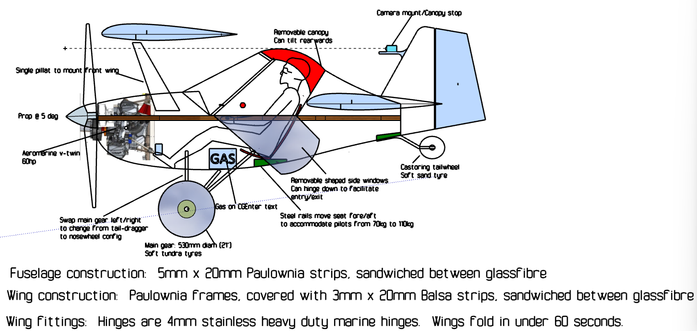
The circled bit is the fixture in question.  It protrudes from the fin with a rubber tip to stop the canopy from tilting back too far.  But it ALSO acts as a very convenient mount for a Go Pro (or similar) giving a near-pilot view of the flight (see the dotted line of sight).  And finally, it can house an external antenna for your radio or nav.

Also, notice the way the (optional) side windows fold down to allow easy entry and exit from the cockpit.  Heat shaped, the windows attach to the fuselage, and can be dropped (as shown in the graphic above.  One can fly:
(1) without either a canopy or side windows
(2) with a canopy but no side windows
(3) with both the canopy and the side windows fitted

« Older posts

© 2025 RTFM Aircraft

Theme by Anders NorenUp ↑